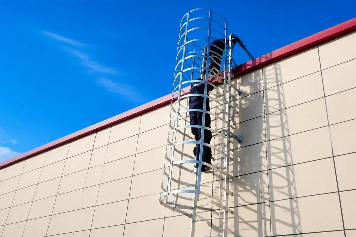
This guide covers the complete installation process for Dengtai fixed steel ladders (FL Series) and caged ladders (CL Series) — from site preparation through final inspection. All instructions assume a structurally sound wall surface (brick, concrete, or structural steel) and compliance with the applicable standard — OSHA 1910.23, EN ISO 14122-4, BS 4211, or AS 1657 — for your jurisdiction.
Important: This guide is a general reference. Always follow the project-specific installation drawings provided with your order. Installation must be performed by competent persons familiar with working at height and power tool operation per OSHA 1910.30 training requirements.
Pre-Installation Checklist
Before beginning installation, verify:
- [ ] Ladder and components received: Verify all ladder sections, brackets, bolts, nuts, washers, and cage components (if applicable) against the packing list
- [ ] No transit damage: Inspect all components for bent stiles, damaged rungs, or coating scratches. Photograph and report damage before installation
- [ ] Wall assessment completed: Confirm the substrate can support ladder and climber dynamic loads. Brick, concrete (minimum C20/25), and structural steel are suitable. For hollow block or aerated concrete, consult a structural engineer
- [ ] Anchors correctly specified: Anchor type and size must match the wall material. Refer to the anchor selection table below
- [ ] Clearance verified: Minimum 200mm (7.9 in) rear clearance per OSHA 1910.23(d)(1) and minimum 381mm (15 in) side clearance from centerline confirmed
- [ ] Top landing prepared: Guardrail or edge protection installed at the roof/platform access point before ladder installation begins per OSHA 1910.28
- [ ] Tools available: Power drill with masonry bits (SDS-plus), torque wrench (calibrated), spirit level (minimum 1,200mm), measuring tape, socket set, MIG welder (only if on-site welding is specified — most Dengtai ladders use bolted connections)
Anchor Selection Guide
| Wall Material | Recommended Anchor | Minimum Embedment | Torque | Standards Reference |
|---|---|---|---|---|
| ————– | ——————- | ——————- | ——– | ——————- |
| Solid concrete (>=C20/25) | M12 wedge anchor (ETA Option 1) or M12 through-bolt | 70mm | 40 Nm | EAD 330232 / ETAG 001 |
| Solid brick (engineering brick) | M12 chemical anchor (epoxy or vinylester resin) | 80mm | Per resin manufacturer ETA | EAD 330499 / ETAG 001-5 |
| Hollow brick / block | M12 through-bolt with sleeve or chemical anchor with mesh sleeve | Per manufacturer ETA | 40 Nm (mechanical) | EAD 330232 |
| Structural steel (>=8mm thick) | M12 Grade 8.8 bolt with nut and washer | Through-hole + 2 threads projection | 80 Nm | ISO 898-1 |
| Aerated concrete / lightweight block | Specialist anchor system required — consult structural engineer | — | — | — |
Do not use: plastic wall plugs, general-purpose screws, or any fixing not rated for the structural load. A single bracket supports a dynamic load that may exceed 1,500 N (337 lbf) during use per the ladder load analysis.
Installation Steps
Step 1: Mark Bracket Positions
1. From the base level, measure upward to the position of the first bracket. Position the first bracket approximately 500mm above the base of the ladder stiles.
2. Measure subsequent bracket positions at a maximum of 2,000mm vertical intervals (1,800mm for heavy-duty Q345B ladders).
3. Use a plumb line or laser level to ensure all bracket positions are vertically aligned. The ladder must be installed plumb — any deviation concentrates stress on individual brackets.
4. Mark all bracket hole positions clearly. Verify against the ladder’s actual bracket spacing (brackets may have shipped pre-spaced).
Step 2: Install Wall Brackets
1. Drill holes at marked positions using the drill bit diameter specified by the anchor manufacturer’s ETA document.
2. Clean holes thoroughly: compressed air blow-out pump, followed by a nylon brush (3 strokes minimum), followed by a second blow-out. Residue reduces anchor capacity by up to 60% per anchor research.
3. Insert anchors and tighten to the specified torque. Do not under-torque (reduced capacity) or over-torque (anchor body fracture).
4. Verify each bracket is level and plumb before proceeding to ladder mounting.
Step 3: Mount Ladder Sections
For single-section ladders (up to 6m):
1. With two installers, lift the ladder into position and engage the stiles with the wall brackets.
2. Insert bolts through bracket-to-stile connections. Hand-tighten all bolts.
3. Verify the ladder is plumb using a spirit level on both stiles.
4. Once plumb is confirmed, torque all bracket bolts to specification.
5. Verify the top extension extends at least 1,100mm above the landing surface per OSHA 1910.23(d)(4)(iv) and EN ISO 14122-4 section 4.2.
For multi-section ladders (6m+):
1. Install the bottom section first, following the single-section procedure above.
2. Lift the next section into position above. Align the flanged joint.
3. Insert all flange bolts and hand-tighten.
4. Attach the upper section to its wall brackets.
5. Verify alignment — the joint between sections must be straight with no kink or angular offset exceeding 1 degree.
6. Torque all flange bolts, then torque all bracket bolts.
7. Repeat for each additional section.
Step 4: Install Safety Cage (CL Series Only)
1. The cage assembly may be pre-installed at the factory or supplied as a separate kit per your order specification.
2. If supplied separately, mount hoops starting from the bottom, connecting each hoop to the five vertical straps using the supplied M8 bolts and lock nuts.
3. Verify hoop spacing is uniform at 300mm intervals.
4. Verify the cage flare at the bottom is correctly oriented (flared outward by 100-150mm per OSHA 1910.23(d)(4) guidance).
5. Verify the cage extends to at least 1,100mm above the top landing per OSHA 1910.23(d)(4)(iv).
6. Tighten all cage connections to 20 Nm.
Step 5: Install Landing Platform and Accessories
1. If the order includes an intermediate landing platform, mount it at the specified height using supplied brackets and fixings.
2. Install platform guardrails on all open sides (1,100mm top rail, intermediate rail at 550mm, 100mm toe board) per EN ISO 14122-4 section 4.3.2.
3. If a security gate is supplied, mount it at the base aligned with the stiles.
4. If an anti-climb shield is supplied, mount it at the specified height above the base.
Step 6: Final Inspection
- [ ] Ladder is plumb (check both stiles with 1,200mm spirit level)
- [ ] All bracket bolts torqued to specification
- [ ] Top extension >=1,100mm above landing
- [ ] Rear clearance >=200mm along entire length per OSHA 1910.23(d)(1)
- [ ] Side clearance >=381mm (15 in) on each side of centerline per OSHA 1910.23(d)(1)
- [ ] Cage hoops at uniform 300mm spacing (if applicable)
- [ ] Cage flare correctly oriented at bottom with 100-150mm outward flare (if applicable)
- [ ] Landing platform guardrails installed and secure (if applicable)
- [ ] No sharp edges, burrs, or coating damage from handling
- [ ] Wall anchors show no signs of cracking or spalling around drill holes
Document the installation: photograph the completed installation, record the date, installers’ names, and anchor type used. File with the building’s safety documentation per OSHA 1910.23(b)(9) inspection requirements.
Safety During Installation
- Installers must use appropriate fall protection when working at height during ladder installation per OSHA 1910.28
- Never stand on an unsecured ladder section
- Never leave ladder sections temporarily propped against a wall — secure to at least two brackets before releasing
- Use mechanical lifting equipment (crane, winch, or pulley) for ladder sections exceeding 50 kg (110 lbs) or lengths over 4m
- Wear appropriate PPE: safety helmet (ANSI Z89.1), safety glasses (ANSI Z87.1), cut-resistant gloves, and steel-toe boots (ASTM F2413)
Post-Installation: Handover Documentation
Provide the building owner or facilities manager with:
1. Installation record (date, installers, anchor specification, photographs)
2. Manufacturer’s Declaration of Conformity
3. Material certificates (EN 10204 Type 3.1) and weld inspection reports (ISO 5817)
4. Inspection and maintenance schedule (annual visual inspection recommended per OSHA 1910.23(b)(9))
5. Manufacturer contact for spare parts and technical support
Download Printable Installation Checklist (PDF) ->
Frequently Asked Questions
Can I install a fixed ladder myself, or do I need a professional?
Installation can be performed by competent persons with experience in structural fixings and working at height. For single-section ladders up to 4m on a ground-level wall, two competent installers can complete the installation in 2-3 hours. For taller or multi-section ladders, use a professional installer — incorrect installation can result in structural failure and serious injury. Per OSHA 1910.30, employers must ensure installers are trained in hazard recognition and safe work practices.
What if the wall surface is uneven?
Minor irregularities (up to 5mm) are accommodated by the bracket-to-stile bolt clearance. For larger irregularities (5-15mm), the bracket base plate requires shimming with steel shims of appropriate thickness. Never use wooden wedges or plastic spacers, which compress over time and create loose connections.
Can ladders be installed on metal cladding or insulated sandwich panels?
Generally, no. Lightweight cladding and insulated panels are not designed to support the concentrated loads from ladder brackets (which may exceed 1,500 N per bracket). The ladder must be anchored to the structural framework behind the cladding. Provide wall construction details to our engineering team for a custom bracket and standoff design if your project requires ladder attachment to a cladded building.
How do I install a ladder on a curved surface (silo, tank, chimney)?
Curved surfaces require custom brackets with a radius-matching base plate. Provide the surface radius measurement and wall material to our engineering team during the quotation stage so the brackets are fabricated to match the exact curvature.
What maintenance is required after installation?
Annual visual inspection: check bracket tightness, inspect for coating condition and corrosion, verify cage integrity, test rung stability. For ladders in corrosive environments (coastal, chemical, water treatment), increase inspection frequency to every 6 months. Download the maintenance inspection checklist. Document all inspections per OSHA 1910.23(b)(9).
Need Installation Support?
Download our detailed installation manual with anchor specifications, torque tables, and troubleshooting guide. Or contact our engineering team.
Email: sales@dtsteelladder.com
WhatsApp: +86 155 1187 9488
Download Installation Manual (PDF) -> | Talk to Our Engineers ->