Author: Jouth Zhao, Senior Engineer, Dengtai Staircase Manufacturing Co., Ltd. | Last updated: May 27, 2026 | Reading time: 7 min
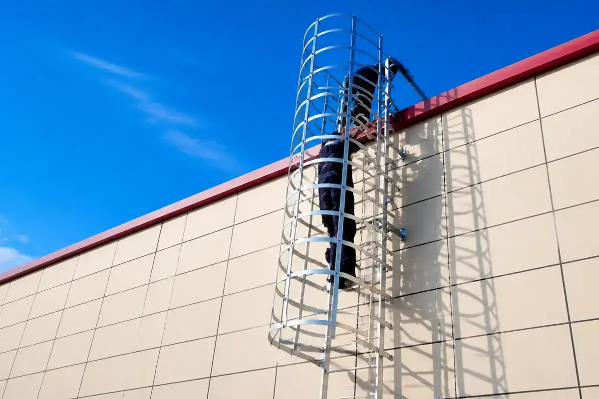
A caged safety ladder installed on an exterior wall is a wind-catching structure. The cage hoops and vertical straps present approximately 40-60% more wind area than an uncaged ladder of the same height. In regions with design wind speeds exceeding 40 m/s (90 mph, equivalent to ASCE 7 Risk Category II), wind load — not the climber’s weight — becomes the governing load case for bracket and anchor design.
This article provides a practical wind load calculation methodology for fixed and caged ladders, aligned with ASCE 7 (USA), EN 1991-1-4 (Europe), and AS/NZS 1170.2 (Australia/New Zealand). No advanced structural engineering background is assumed — the formulas are reduced to plug-in values.
Why Wind Load Matters for Ladders
| Ladder Height | Wind Speed | Wind Force on Caged Ladder (approx.) | Impact |
|---|---|---|---|
| ————– | ———– | ————————————– | ——– |
| 6m | 40 m/s (90 mph) | 1.2 kN | Standard brackets typically adequate |
| 10m | 40 m/s (90 mph) | 2.0 kN | Verify bracket capacity |
| 15m | 50 m/s (112 mph) | 4.5 kN | Bracket reinforcement likely needed |
| 20m | 60 m/s (134 mph) | 9.6 kN | Requires structural brackets + seismic/wind bracing |
For ladders exceeding 10m in wind-prone regions, wind load analysis is not optional — it is required by ASCE 7 and EN 1991-1-4 for any “other structure” attached to a building.
Step 1: Determine Design Wind Speed
USA (ASCE 7-22)
Use the ASCE 7 Hazard Tool (https://asce7hazardtool.online/) to obtain the basic wind speed V for your project location, or use the map in ASCE 7-22 Figure 26.5-1.
| Risk Category | Description | MRI (years) | Typical V (mph) |
|---|---|---|---|
| ————– | ————- | ————- | —————– |
| I | Low hazard (agricultural, temporary) | 300 | 105-120 |
| II | Standard (commercial, industrial) | 700 | 115-135 |
| III | High hazard (schools, assembly) | 1,700 | 120-145 |
| IV | Essential (hospitals, fire stations) | 3,000 | 125-150 |
Europe (EN 1991-1-4)
The fundamental basic wind velocity vb,0 is obtained from the National Annex for the country of installation. For quick reference:
| Country | vb,0 (m/s) | Notes |
|---|---|---|
| ——— | ———– | ——- |
| UK | 22-30.5 | Depends on altitude and location |
| Germany | 22.5-30.0 | Wind zone dependent |
| Netherlands | 24.5-29.5 | Coastal higher |
| France | 22-28 | Zone dependent |
Australia/New Zealand (AS/NZS 1170.2)
Regional wind speeds V_R are specified for each wind region:
| Region | V_R (m/s) | Description |
|---|---|---|
| ——– | ———- | ————- |
| A (non-cyclonic) | 30-45 | Most of Australia |
| B (non-cyclonic) | 45-57 | Coastal |
| C (cyclonic) | 57-70 | Northern Australia coastal |
| D (cyclonic) | 70-88 | Severe tropical cyclone |
Step 2: Calculate Wind Pressure
The basic formula for wind pressure q on a structure is:
q = 0.613 × V² (SI units, q in Pa, V in m/s)
Or in US customary units:
q = 0.00256 × V² (psf, V in mph)
For a caged ladder, the force coefficient Cf depends on the geometry:
| Ladder Configuration | Force Coefficient Cf |
|---|---|
| ——————— | ——————— |
| Uncaged ladder (round rungs) | 1.2 |
| Uncaged ladder (flat rungs) | 1.6 |
| Caged ladder (round members) | 1.4 |
| Caged ladder (flat strap members) | 1.8 |
| Ladder with solid back/side panel | 2.0 |
Step 3: Calculate Projected Wind Area
The projected area is the area of the ladder and cage that the wind “sees” from its worst direction (typically perpendicular to the wall).
Uncaged Ladder:
A_projected = H × W × S
Where:
- H = ladder height (m)
- W = ladder width (m), typically 0.6m
- S = solidity ratio (ratio of solid area to envelope area)
– Uncaged ladder with round rungs at 300mm spacing: S ≈ 0.15
– Uncaged ladder with flat rungs: S ≈ 0.25
Caged Ladder:
A_projected = H × [(W × S_ladder) + (D_cage × S_cage)]
Where:
- D_cage = cage diameter (m), typically 0.8m
- S_cage = solidity ratio of cage (hoops + vertical straps)
– Hoops at 300mm spacing with 20mm flat bar: S ≈ 0.20
– Add 0.05 for each set of vertical straps
Example calculation (6m caged ladder, 600mm width, 800mm cage):
- A_ladder = 6.0 × 0.6 × 0.15 = 0.54 m²
- A_cage = 6.0 × 0.8 × 0.20 = 0.96 m²
- A_total = 0.54 + 0.96 = 1.50 m²
Step 4: Calculate Total Wind Force
F_wind = q × Cf × A_projected
Example: 6m caged ladder, V = 45 m/s (100 mph)
- q = 0.613 × 45² = 1,241 Pa
- Cf = 1.4 (caged, round members)
- A_projected = 1.50 m²
- F_wind = 1,241 × 1.4 × 1.50 = 2,606 N = 2.61 kN
Example: 10m caged ladder, V = 50 m/s (112 mph)
- q = 0.613 × 50² = 1,533 Pa
- Cf = 1.4
- A_projected = 10 × [(0.6 × 0.15) + (0.8 × 0.20)] = 10 × 0.25 = 2.50 m²
- F_wind = 1,533 × 1.4 × 2.50 = 5,366 N = 5.37 kN
Step 5: Distribute Wind Force to Brackets
The total wind force is distributed to brackets proportionally to their tributary area:
F_bracket_i = F_wind × (S_i / H)
Where S_i = bracket spacing (m). For equally spaced brackets: F_per_bracket = F_wind / n, where n = number of brackets.
The top bracket typically serves a larger tributary area (the top half of the spacing above the last full-height bracket span plus the extension above the landing). Verify, or conservatively multiply the top bracket force by 1.5.
Step 6: Verify Bracket and Anchor Capacity
Compare the calculated bracket force against the manufacturer’s rated capacity.
Dengtai Standard Bracket Capacities (per bracket, factor of safety = 3.0):
| Bracket Type | Lateral Capacity (kN) | Pull-Out (kN) |
|---|---|---|
| ————- | ———————- | ————— |
| Standard HDG wall bracket | 5.0 | 4.0 |
| Heavy-duty HDG bracket | 8.0 | 6.5 |
| SS304 bracket | 6.0 | 5.0 |
If F_bracket_i > rated capacity, options are:
1. Reduce bracket spacing (add intermediate brackets)
2. Specify heavy-duty brackets
3. Request a custom bracket design from the manufacturer
FAQ: Wind Load Calculations
Q: When is wind load analysis mandatory for ladder specification?
For any exterior ladder exceeding 10m in height, wind load analysis is required by structural codes (ASCE 7, EN 1991-1-4). For ladders under 10m in standard wind zones (< 40 m/s), standard bracket designs typically have sufficient margin. However, for ladders in hurricane/cyclone zones, analysis is recommended for any height above 6m.
Q: Does a cage increase wind load significantly?
Yes. A cage increases the projected wind area by 40-60% compared to an uncaged ladder. The cage hoops act as additional wind-catching elements. This is the primary reason that cage ladder brackets must be verified for wind load.
Q: Does wall proximity reduce wind load?
No. A ladder mounted on a wall experiences approximately the same wind load as a free-standing ladder because the wall creates a stagnation zone that increases local wind pressure. ASCE 7 treats wall-mounted structures as components and cladding (C&C) with higher pressure coefficients than free-standing structures in some configurations.
Q: Can Dengtai perform the wind load calculation for my project?
Yes. Provide your project location (address or coordinates), ladder height and configuration, and the applicable design code (ASCE 7, EN 1991-1-4, or AS/NZS 1170.2) with your quotation request. Dengtai’s engineering team will include the wind load analysis in the quotation package at no additional charge.
Q: How does wind load affect ladder selection vs stairs?
For roof access ladders in high-wind zones, wind-induced vibration and the force on the climber can make ladder use uncomfortable or unsafe in certain wind conditions. If the ladder will be used during windy conditions (e.g., for emergency roof access during a storm), consider whether stairs would be a safer alternative.
Quick-Reference Table: Wind Force per Meter of Ladder Height
| Wind Speed | Uncaged (kN/m) | Caged (kN/m) |
|---|---|---|
| ———– | ————— | ————- |
| 30 m/s (67 mph) | 0.04 | 0.06 |
| 40 m/s (90 mph) | 0.07 | 0.11 |
| 50 m/s (112 mph) | 0.10 | 0.17 |
| 60 m/s (134 mph) | 0.15 | 0.24 |
| 70 m/s (157 mph) | 0.20 | 0.33 |
Multiply by ladder height (m) for total wind force in kN. Values assume standard 600mm width caged ladder with round members.
Key Takeaways
1. Wind load is the governing design case for exterior ladders >10m in wind-prone regions
2. A cage increases wind load by 40-60% vs an uncaged ladder — factor this into bracket design
3. The formula is simple: F_wind = q × Cf × A_projected — you can perform the calculation with basic data
4. Verify bracket capacity against calculated force — if the force exceeds capacity, reduce spacing or upgrade brackets
5. Include wind load analysis in your RFQ — Dengtai provides this as a standard service
Related Resources
- Ladder Fall Protection Systems →
- Fixed Ladder Requirements OSHA →
- How to Read Ladder Engineering Drawings →
- OSHA vs EN 14122 Standards Comparison →
- Installation Guides →
Send your project location and ladder specification. Dengtai’s engineering team will perform the wind load analysis and confirm bracket adequacy — included with every quotation.
Frequently Asked Questions
1. At what building height do wind loads become a genuine concern for ladders?
Wind loads increase with height above ground, roughly proportional to the velocity pressure exposure coefficient Kz. At 10 stories (30m), wind pressure is approximately 2× ground level. At 20 stories (60m), it is approximately 2.5×. At 40 stories (120m), approximately 3×. As a rule of thumb: for buildings under 10 stories, standard ladder brackets and anchors are almost always adequate. For 10-20 stories, confirm with a quick wind load check. Above 20 stories, require a formal wind load calculation.
2. Does the cage increase or decrease wind load?
The cage increases the wind-catching area of the ladder by approximately 40-60%, depending on hoop diameter and spacing. The cage acts as a semi-permeable cylinder — it does not fully block wind, but it creates additional drag. In wind load calculations, the force coefficient Cf for a caged ladder is approximately 1.4-1.8 (compared to 1.2-1.6 for an uncaged ladder). The cage is a real structural load contributor and must be included in the analysis.
3. Can I use the same anchor type for a wind-exposed ladder as an interior ladder?
Not automatically. Wind creates uplift forces that chemical anchors and wedge anchors resist differently. Wedge anchors in concrete perform well under tension (uplift) but require a minimum edge distance. Chemical anchors provide better performance in tension if properly installed, but require cure time monitoring. For ladders on tall buildings, specify the anchor type, embedment depth, and edge distance based on the calculated wind loads — do not default to a “standard anchor” from an interior installation specification.
About the Author
Jouth Zhao is Senior Engineer at Dengtai Staircase Manufacturing Co., Ltd., with expertise spanning 500+ industrial ladder projects across 50+ countries. He regularly advises engineers, procurement managers, and facility owners on specification, compliance, and installation best practices.
Email: sales@dtsteelladder.com
WhatsApp: +86 155 1187 9488
>ASCE 7-22()EN 1991-1-4()——→→→。、、、40(Kz=1.31, qz=1.58 kN/m², F=4.2 kN)。。